
Contents
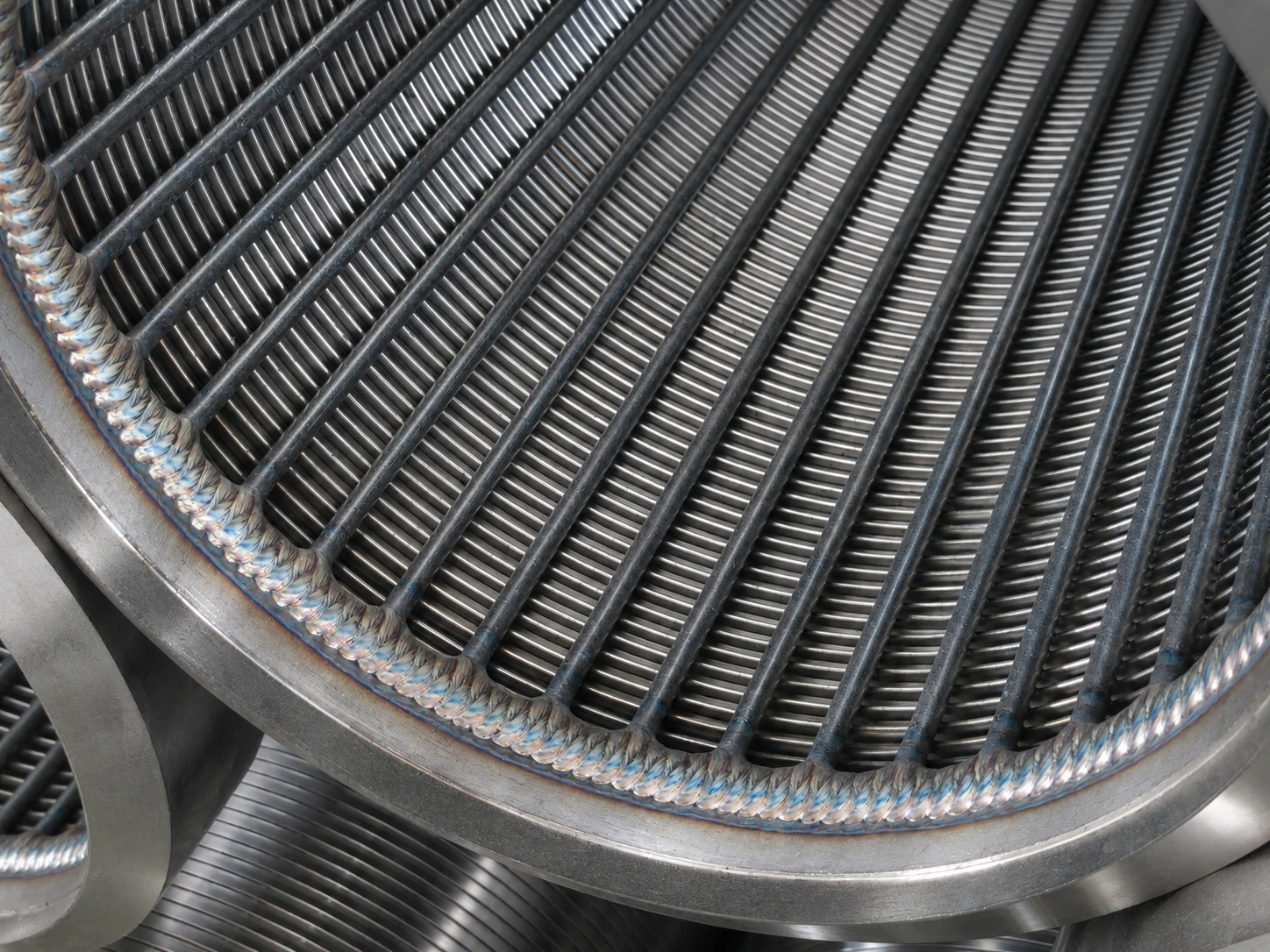
Well screen open area describes the openings available for water entry. It is useful when comparing screen constructions, but it does not tell you how much water an aquifer can sustainably supply. A meaningful review connects screen geometry to the completed well, the intended pumping rate and the assumptions used in the hydraulic assessment. [1][2]
Before comparing two percentages, ask what area each percentage represents and whether both suppliers used the same calculation basis.
Define the area before using it
For a cylindrical screen, a preliminary calculation may express geometric open area as the active cylindrical surface area multiplied by the opening fraction. The underlying dimensions must be consistent: active length, reference diameter and the definition of the opening fraction.
Ask whether support elements, blank sections and connection lengths are included or excluded. If two suppliers use different conventions, restate the calculations on a common basis before drawing a conclusion.
An overall assembly length is easy to misunderstand. A six-metre assembly does not necessarily contain six metres of active openings. Put both dimensions on the comparison sheet.
Distinguish geometric area from effective entrance area
The full geometric opening area is not necessarily equally available to incoming water after installation. The surrounding formation or pack, distribution of inflow and condition of the well influence the flow path. Deposits or incomplete development can also affect performance. [2][3]
An engineer may therefore use an effective entrance area when evaluating velocity. Any reduction from geometric area should be stated and justified for the project. Do not silently apply a fixed usable-area percentage taken from another well.
This distinction is a reason to document assumptions, not a reason to dismiss a manufacturer's open-area figure. The geometry is useful; it simply answers a narrower question than completed-well performance.
Read the entrance-velocity calculation correctly
The basic relationship is:
Average entrance velocity = flow rate ÷ effective entrance area.
The following numbers are hypothetical and illustrate arithmetic only. They are not OFD product ratings or a recommended well design.
Assume a flow of 36 m³/h, equivalent to 0.010 m³/s. With an assumed effective entrance area of 0.50 m², the calculated average velocity is:
0.010 ÷ 0.50 = 0.020 m/s.
If the effective area in the same example is only 0.25 m², the calculated average becomes:
0.010 ÷ 0.25 = 0.040 m/s.
Halving the assumed area doubles the calculated average velocity at the same flow. The calculation does not establish whether either case is acceptable, whether inflow is uniform or whether the aquifer can supply that rate. Those are separate design questions.
Keep entrance velocity separate from pipe velocity
Water entering through screen openings and water moving upward inside the well use different flow areas. The internal pipe cross-section cannot be substituted for the total screen opening area in an entrance-velocity calculation. Likewise, an entrance-velocity figure should not be presented as the velocity throughout the casing. [2][3]
When reviewing a calculation, label each area and velocity explicitly. This makes unit mistakes and mismatched assumptions easier to spot, especially when quotations combine metric and US customary units.
Ask what evidence supports the proposed pumping rate
A screen's hydraulic description is one input to a well design. The producing interval, aquifer response, construction and development also affect the result. Pumping tests provide information about the completed well under the test conditions; a catalogue figure cannot replace them. [2][3]
For a proposed screen, keep its geometry, the project's hydraulic assessment and the planned performance test as separate review items. Mechanical capacity belongs in a separate review as well. High open area does not demonstrate adequate collapse or connection strength.
OFD's water well screen range can be reviewed against a project's approved requirements. Send the active length, dimensions, slot specification and intended flow to OFD, together with the designer's calculation basis. The slot-size guide covers the retention information that should accompany the hydraulic review.
References
[1] Johnson Screens, Stainless Steel Water Well Screens and Accessories. Source
[2] USDA NRCS, National Engineering Handbook, Part 650, Chapter 12: Springs and Wells. Source
[3] University of Florida IFAS Extension, Water Wells for Florida Irrigation Systems. Source